Basic Switch Input Questions

Discussion and support for MoTeC Power Distribution Modules

Basic Switch Input Questions

Postby CNDat510 on Sat Nov 26, 2016 11:48 am

Sorry, I'm starting really basic here.

Can anyone explain, confirm, or deny the two possible scenarios of the attached schematic?
This will assume PDM is on, and the switch at point (F) is open. The red lettering is mine. You might need to scroll a bit to see the whole picture.

Screen Shot 2016-11-25 at 10.20.51 AM.png
Screen Shot 2016-11-25 at 10.20.51 AM.png (41.12 KiB) Viewed 21120 times


Scenario A
Points (A) through (F) are seeing some type of current flow.
If this statement is true, the CPU is making a ground somewhere at (H?) to allow current to flow from +Batt to point (E) where it is being monitored by the CPU.
When the switch at (F) is closed, electricity follows the path of least resistance to 0V at point (G).
The CPU sees a change in state at (E) and executes Logic Condition as programed.

Scenario B
There is no current measured at (A) through (F).
Only until the switch closes at point (F) does the circuit ground itself, which then allows current to flow from +Batt to 0V at point (G).
The CPU is now able to monitor the current at (E) and executes Logic Condition based on programing.

Or, is there a Scenario C?
CNDat510
 
Posts: 18
Joined: Mon Nov 21, 2016 12:03 pm

Re: Basic Switch Input Questions

Postby CNDat510 on Sat Nov 26, 2016 11:54 am

I've watched the PDM video seminar, read the PDM manual, and searched the forums, but can't seem to get much clarity to the following section in the manual regarding Input Wiring (numbering is mine):

1.
The PDM Switch Inputs are intended for use with a switch that is directly wired between a PDM input pin and a PDM 0 V pin. Each input has an internal 10 kilo-ohm pull-up resistor to Batt+.

2.
If it is required to connect a switch that is wired to another system in the vehicle, ensure that the voltage levels are set appropriately as there may be ground voltage variations between devices. Tip: If standby current is important, wire the switches so that they are normally open during standby. This will reduce the standby current.

3.
When an input is driven from a device that switches to battery, the switch should if possible, be rearranged so that it switches to 0 V.

4.
If the signal comes from an electronic device such as an ECU that has an output that can only switch to battery (e.g. a signal that indicates when to turn the fuel pump on), this might not be possible. In this case an external pull- down resistor is required. The resistor should be 1500 ohm 0.25 watt and should be connected between the input pin and the 0 V pin. The input trigger levels should be set to 4 V and 5 V to guarantee correct triggering for all possible battery voltages.


Does anyone have a schematic of #2-4? I understand general principle of #1.
CNDat510
 
Posts: 18
Joined: Mon Nov 21, 2016 12:03 pm

Re: Basic Switch Input Questions

Postby CNDat510 on Sat Nov 26, 2016 11:59 am

Is this schematic a possible example of #3, with or without resistor at point (I)?
The specs say the Input Pins can take up to 51V, so that would lead me to believe you could put 12V straight in without an issue?

Screen Shot 2016-11-25 at 10.20.51 AM copy.png
Screen Shot 2016-11-25 at 10.20.51 AM copy.png (44.85 KiB) Viewed 21119 times
CNDat510
 
Posts: 18
Joined: Mon Nov 21, 2016 12:03 pm

Re: Basic Switch Input Questions

Postby Scott@FP on Sat Nov 26, 2016 2:43 pm

The pullup is the 10K resistor 'C'. With the switch open, the ECU input pin sees B+ voltage. With the switch closed, the ECU sees 0v (or very close to it).
Scott@FP
 
Posts: 421
Joined: Thu Jul 10, 2008 7:57 pm

Re: Basic Switch Input Questions

Postby the_bluester on Sat Nov 26, 2016 3:24 pm

To expand a little. You will find that the input impedance is quite high (Point E) and with the switch on or off the current involved is negligible. I suspect that the input will be effectively open circuit when the switch is off, and even if you had grounded inputs for all 16 fixed inputs the total current being switched (with 10K Ohm pull up resistors) will be about 2 milliamps.

The input switches based on voltage rather than current.
the_bluester
 
Posts: 210
Joined: Wed Nov 04, 2015 9:30 am

Re: Basic Switch Input Questions

Postby adrian on Mon Nov 28, 2016 11:57 am

What exactly is it that you are trying to do/find out?

Scenario A is roughly right, there will be a very small current flow (micro Amp range) through some of the additional circuitry on the board. The ADC simply measures the voltage at the pin and that is then used in the logic programmed via PDM Manager.

The easiest way to switch an input is directly to 0V, the internal 10k pull up resistor then gives you the two required states. You can also switch directly to the battery or another voltage source up to 51V. The only issue is because of the internal pull up resistor when you open your switch the pin voltage stays high. That is why you need a 1.5k pull down resistor. So your 12V input should be more like this:

PDM Input.png
PDM Input.png (34.68 KiB) Viewed 21081 times
adrian
MoTeC
 
Posts: 719
Joined: Mon Apr 13, 2015 5:16 pm

Re: Basic Switch Input Questions

Postby CNDat510 on Mon Nov 28, 2016 5:03 pm

[quote=“Scott@FP"]The pullup is the 10K resistor 'C'. With the switch open, the ECU input pin sees B+ voltage. With the switch closed, the ECU sees 0v (or very close to it).[/quote]

the_bluester wrote:To expand a little. You will find that the input impedance is quite high (Point E) and with the switch on or off the current involved is negligible. I suspect that the input will be effectively open circuit when the switch is off, and even if you had grounded inputs for all 16 fixed inputs the total current being switched (with 10K Ohm pull up resistors) will be about 2 milliamps.

The input switches based on voltage rather than current.


Thanks guys, I now understand the workings of the native input switch a bit better. Admittedly I’m a complete novice when it comes to electronics and wiring so I’m in a bit of a learning phase.

[quote=“adrian"]What exactly is it that you are trying to do/find out?

Scenario A is roughly right, there will be a very small current flow (micro Amp range) through some of the additional circuitry on the board. The ADC simply measures the voltage at the pin and that is then used in the logic programmed via PDM Manager.

The easiest way to switch an input is directly to 0V, the internal 10k pull up resistor then gives you the two required states. You can also switch directly to the battery or another voltage source up to 51V. The only issue is because of the internal pull up resistor when you open your switch the pin voltage stays high. That is why you need a 1.5k pull down resistor. So your 12V input should be more like this:[/quote]

Thanks Adrian, your schematic is very helpful. This covers #4 in my second post above, correct? How does #3 differ from #4, or are they the same?

Any chance you could give an example for the need of a "standby current” as noted in #2?

Here’s my project:
viewtopic.php?f=42&t=3450

As I mention in that thread, I’m going to be doing a bit of a sleeper install while attempting to utilize the OEM switches. Some of these will remain integrated with the dash harness, while others will be removed from the harness and converted to simple switches.

The ignition switch used to receive full power to Pin 1 and distribute through the other pins. I will now instead be mapping Pin 1 to 0V and wire discrete Motec Inputs to the other pins.

Some OEM circuits are completed by going to ground, such as my high beam headlights and horn. Some switches send a full 12 volts.

The design objective is to have all OEM switches operational in their traditional way, but also program the keypad to do some of the same work (i.e. start car, flash high beams, etc, )
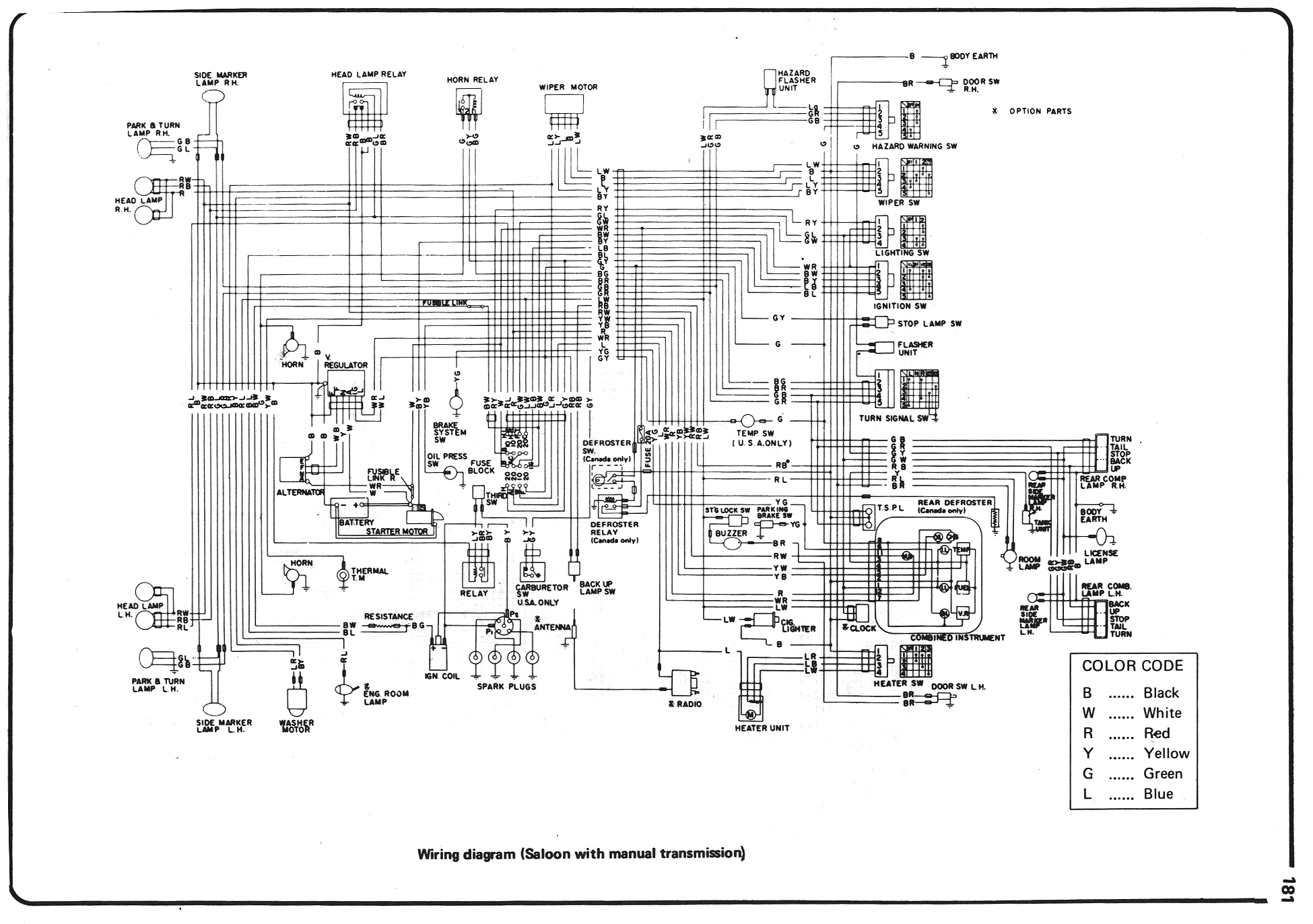
510 Wiring.jpg
510 Wiring.jpg (840.6 KiB) Viewed 21074 times


Motec Pin Out - PDM15 (Power Distribution Module).pdf
(856.62 KiB) Downloaded 964 times


Thanks
CNDat510
 
Posts: 18
Joined: Mon Nov 21, 2016 12:03 pm

Re: Basic Switch Input Questions

Postby adrian on Tue Nov 29, 2016 8:37 am

Thanks Adrian, your schematic is very helpful. This covers #4 in my second post above, correct? How does #3 differ from #4, or are they the same?

#3 is just talking about modifying the switch layout so you have the preferred 0V switching setup. This isn't really necessary you can switch 12V no problem, you just have to weigh up whether it is easier to rewire the switch or add a pull down resistor.

Any chance you could give an example for the need of a "standby current” as noted in #2?

As you have the PDM connected directly to the battery there will always be a very small current draw. The only time this becomes much of an issue is if you have switches that are normally closed. So for example if you have a switch that is normally closed when the car is off you end up with a current path from the battery through the 10k pull up through your switch then to ground (see below).

PDM NC Switch.png
PDM NC Switch.png (31.13 KiB) Viewed 21064 times


You only have 1-1.5mA flowing but if you have a number of them setup this way you might find you start having issues with the battery draining.
adrian
MoTeC
 
Posts: 719
Joined: Mon Apr 13, 2015 5:16 pm

Re: Basic Switch Input Questions

Postby CNDat510 on Tue Nov 29, 2016 10:03 am

adrian wrote:
Thanks Adrian, your schematic is very helpful. This covers #4 in my second post above, correct? How does #3 differ from #4, or are they the same?

#3 is just talking about modifying the switch layout so you have the preferred 0V switching setup. This isn't really necessary you can switch 12V no problem, you just have to weigh up whether it is easier to rewire the switch or add a pull down resistor.

Any chance you could give an example for the need of a "standby current” as noted in #2?

As you have the PDM connected directly to the battery there will always be a very small current draw. The only time this becomes much of an issue is if you have switches that are normally closed. So for example if you have a switch that is normally closed when the car is off you end up with a current path from the battery through the 10k pull up through your switch then to ground (see below).

PDM NC Switch.png


You only have 1-1.5mA flowing but if you have a number of them setup this way you might find you start having issues with the battery draining.


Excellent, very helpful and much appreciated!
Cory
CNDat510
 
Posts: 18
Joined: Mon Nov 21, 2016 12:03 pm


Return to PDM15 PDM16 PDM30 and PDM32

Who is online

Users browsing this forum: No registered users and 3 guests