Sequential Turbo Setup

Discussion and Support for MoTeC's M1 series ECUs

Sequential Turbo Setup

Postby CarloL on Wed Oct 19, 2016 7:56 am

Question: Can somebody explain to me how Sequential Turbo Setup works on an M1, curious how it is Sequential as opposed to running in parallel?


Car: Toyota Supra 2JZGTE

Firmware: https://1drv.ms/u/s!Ao-FTTt3GMhrg4RGM1jTZZ0Ifn6c2g

OEM(Toyota) How it works

Actuators and VSVs:

They are not pulse width modulated except for the wastegate one. So the other 3 are either open or closed. The wastegate one is PWM controlled.

There are four VSV/actuator assemblies that control the sequential turbo operation:
[*]Intake Air Control Valve (IACV) --on/off
[*]Exhaust Gas Control Valve (EGCV)-- on/off
[*]Exhaust Gas Bypass Valve (EGBV)-- on/off
[*]Wastegate --PWM

VSVs switch manifold pressure (boost) to and away from actuators. The actuators open/shut valve butterfly flaps.

IACV
When this switches, boost generated by #2 turbo is allowed to join the intake stream
When it isn't switched, there is a small flap in the IACV assembly that allows any boost generated by #2 turbo as it prespools to join the intake stream, preventing turbo stall.

EGCV
This allows exhaust gas to flow through #2 turbo, causing it to spin up. When it's shut, there is no gas flow through the impeller of #2 turbo and therefore it doesn't spin.

EGBV
This allows some exhaust gas to bypass the EGCV and join the output of the first turbo. It serves two purposes - one, it prespools the second turbo by allowing some exhaust gas flow through it. Two, it controls the amount of exhaust gas going through the first turbo in much the same way as a wastegate - therefore controlling the maximum boost pressure generated by #1 turbo.

Wastegate
This bypasses exhaust gas from the first turbo, lowering the overall amount of exhaust gas going through *both* turbos and controlling the maximum boost pressure generated by both turbos in parallel.

Motec M130

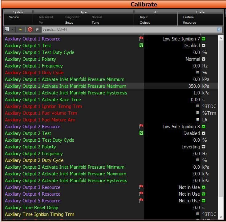
[*]Low Side Ignition 7 -- IACV
[*]Low Side Ignition 8 -- EGCV


My understanding

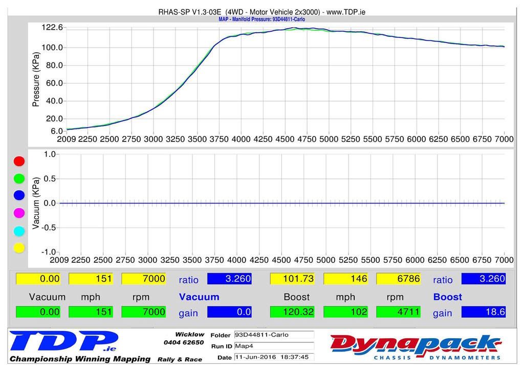
My map has IACV and EGCV set to two Aux outputs , my understanding is the transition is regulated by the Manifold pressure 350kPa , constantly turbo one is working , when Manifold Absolute pressure hits 350kPa , turbo two comes online, I presume the manifold absolute pressure would read xxxkPa at a certain rpm @X% throttle , so when she reads 350kPa you know she is running 70% throttle / 3800rpm so has enough gas to flow turbo 2 , open VSV to allow exhaust gas through? Would gearing come into it, how did you know to choose 350kPa?

Was told this is incorrect the Duty cycle tables control the valves, OEM the transition from 1 to 2 Turbos happens at 3500 rpm


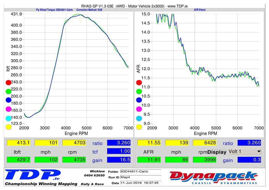
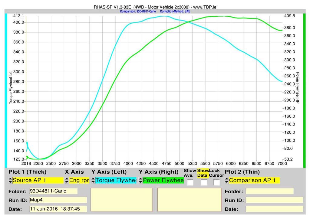
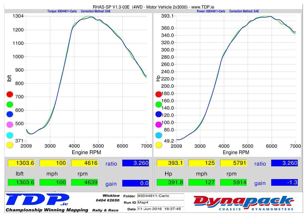
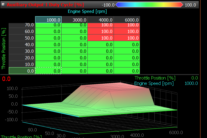
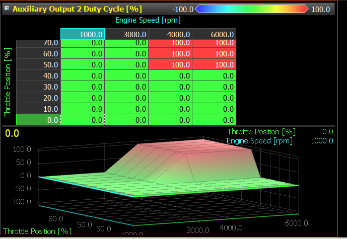
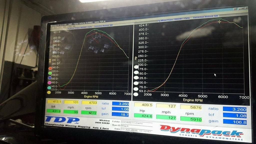
Graph look like parallel operation though, the Duty cycle tables to me run the Turbos in Parallel
Image

Image

Image

Image

Image

Image

Image
Image
Image
Image
CarloL
 
Posts: 105
Joined: Thu Nov 05, 2015 2:00 am

Re: Sequential Turbo Setup

Postby Stephen Dean on Thu Oct 20, 2016 9:18 am

As this is custom code that was written by John Reed Racing, you would have to talk to them directly. With the Partner Packages like JRR's, MoTeC doesn't get the Project (the code behind the Package) only the Package itself, so we do not know what the control strategies are. This is why the support for the Partner Packages is provided by the company that sells the Package.
Stephen Dean
MoTeC Research Centre Melbourne, Australia
User avatar
Stephen Dean
Site Admin
 
Posts: 1717
Joined: Tue Dec 02, 2014 10:29 am
Location: Melbourne

Re: Sequential Turbo Setup

Postby CarloL on Fri Oct 21, 2016 12:03 am

Thanks Stephen

Firmware was written by John but Calibrated by Robbie in TDP
http://www.motec.com/dealerssectionuk/d ... e/#Ireland

Was talking to Robbie yesterday , yes she is running in parallel even though I requested and was assured she will be set to run in sequential ; currently trying to resolve this , yellow warnings and fueling FPR incorrect setting
CarloL
 
Posts: 105
Joined: Thu Nov 05, 2015 2:00 am

Re: Sequential Turbo Setup

Postby CarloL on Tue Jan 16, 2018 8:44 pm

Incase it helps anybody

Hi Carlo,

My memory is a bit rusty on the sequentials but I seem to remember only needed two of the three solenoids. But either way we should have plenty to work with in the package.

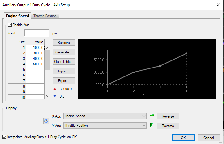
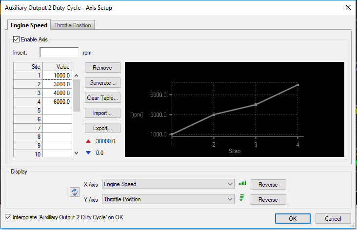
AEM did it very simple based on rpm mostly (and load/throttle) and we can easily do that using the Auxilliary Outputs (I believe you have them highlighted in one of the screen shots). You would set the table axis up (as you had shown) and then simply put 100 in the table where you want that output to be on, and 0 where you want it off. See attached picture.

Also make sure you set the activate parameters appropriately. If it is inlet manifold pressure, set it so the output will come on when you want it to. If you don't want to use those parameters (and just let the table control it) then set the min to 0 and the max to 500 (inlet manifold). Also make sure you setup the fuel and timing trims on Aux 1. Just zero it out if you aren't using them (set mixture aim to 2.0 if not using it).

Hope that helps! Should be pretty easy.


John Reed
CarloL
 
Posts: 105
Joined: Thu Nov 05, 2015 2:00 am


Return to M1 ECUs

Who is online

Users browsing this forum: No registered users and 9 guests