Page 1 of 1
Digital Input - 12V Clutch Switch

Posted:
Sun Jul 24, 2022 10:48 amby ajwithers
I'd like to use my OEM clutch switch as a Driver Input switch to signal if the clutch is engaged. I currently have it wired to pin A23 Digital 1 input on my M150. The clutch switch is wired to 12v batter source and supplies 12v with the key on and the clutch is NOT engaged. When the clutch is engaged the switch circuit is interrupted and "open".
Does this mean the ECU "sees" 12V when the clutch is NOT engaged and a pullup voltage when it's engaged. Or does the pullup also affect the 12v reading?
Thanks in advance, and sorry for the "dumb" question.
Re: Digital Input - 12V Clutch Switch
Posted:
Sun Jul 24, 2022 12:31 pmby iivvaann12
You have capture inputs in m1 tune it will answer all of your questions
Re: Digital Input - 12V Clutch Switch
Posted:
Mon Jul 25, 2022 6:12 amby ajwithers
Thanks, I’ll look at this again, but when I previously looked it only showed the DIG state, and not voltage.
Also to clarify, I'm trying to use DIG1 pin A23 on the M150; this isn't a UDIG input, so don't think it works with the "Capture Inputs" function. I can pull up the Monitor Input/Output function, but this only shows the state for this input i.e. On/Off; and not the voltage.
Also, when in Tune All Calibrate or a page that has the Driver Switch Input tree... the Voltage does not display.
Since the voltage reading (from my voltmeter) is ~13.3v when the clutch is disengaged or 3.3v when engaged, I would have thought that I could use a Threshold = 8.3v (approximately in the middle of the two readings) and a 1v hysteresis. However, whenever I use a voltage above 4v I get a Threshold Maximum warning.
I tried a 4v Threshold with a 0.2v hysteresis and still no luck with it changing the switch state.
I feel so stupid... can't even figure out a simple switch. Any "remedial" material that I can read up on?
Re: Digital Input - 12V Clutch Switch
Posted:
Mon Jul 25, 2022 9:31 amby NathanB
You are using the wrong input for the job.
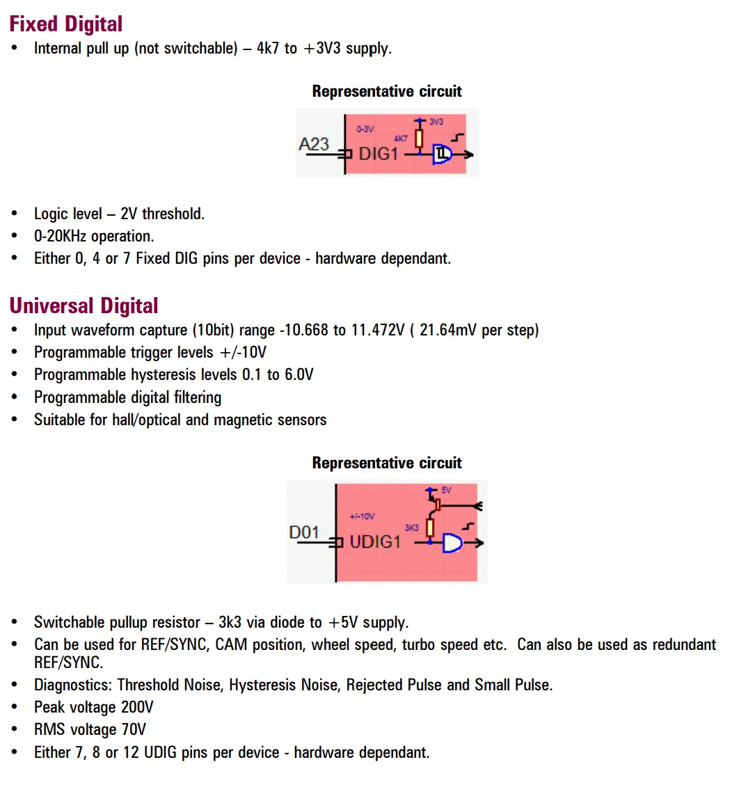
Digital inputs have a fixed pull up, and a 2V logic level threshold.
You need to switch to a UDIG input for your clutch switch.
- Dig V UDIG.jpg (169.29 KiB) Viewed 6333 times
Re: Digital Input - 12V Clutch Switch
Posted:
Mon Jul 25, 2022 1:44 pmby ajwithers
Thank you Nathan… I thought that might be the case. Unfortunately I’m using most of my UDIG inputs. I imagine the alternative them would be to rewire the clutch switch to ground or a 0V from the ECU… correct?
Re: Digital Input - 12V Clutch Switch
Posted:
Mon Jul 25, 2022 4:11 pmby NathanB
You could also use:
- lambda narrowband inputs
- unused knock inputs
- unused peak and hold injector outputs
- unused low side ignition outputs
all have 12 bit adc connected for pin voltage which is used for various diagnostic functions.
They aren't precise enough for sensor inputs (knock and narrowband excluded, although for their specific functions) but for a 12/0V switch they are fine, and are rated for continuous voltage input of over 12V.
If you have none of these spare, yo cold also rewire the switch to gnd if you needed to retain the DIG input, and set thresholds accordingly.