Page 1 of 1

Engine position/reference trace

PostPosted: Sun Dec 13, 2020 1:38 am
by greenamex2
Hi all

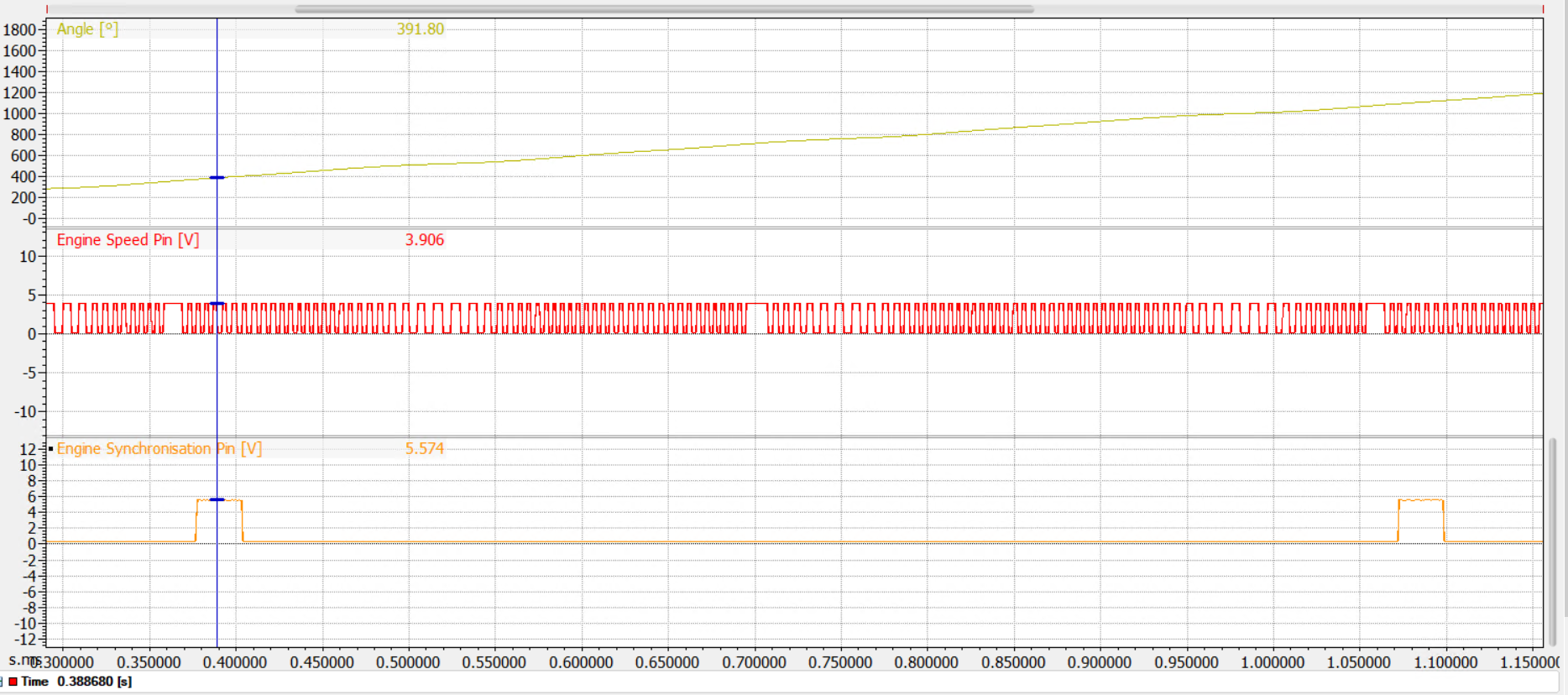
How does my Engine position and reference wave forms look?

Screenshot 2020-12-12 143308.png
And, finally, after 15 years...
Screenshot 2020-12-12 143308.png (272.68 KiB) Viewed 10592 times

Re: Engine position/reference trace

PostPosted: Sun Dec 13, 2020 1:58 am
by greenamex2
ECU view -

Screenshot 2020-12-12 145635.png
Gregs first turnover
Screenshot 2020-12-12 145635.png (1.2 MiB) Viewed 10590 times

Re: Engine position/reference trace

PostPosted: Mon Dec 14, 2020 9:17 am
by Stephen Dean
The Pullups should be on for Hall Effect sensors.

Re: Engine position/reference trace

PostPosted: Mon Dec 14, 2020 8:46 pm
by AlanB
Also, the Hysteresis for ref and sync should be a fixed value for hall effect sensors. I would suggest 1V.

Re: Engine position/reference trace

PostPosted: Mon Dec 14, 2020 8:51 pm
by greenamex2
Thanks all, that is lunch times task.

Is the fact that the speed trace is "inverted" an issue?

I have ordered a sensor to match the reference one but just interested (especially if I need to use a wheel speed sensor in an emergency!).

Re: Engine position/reference trace

PostPosted: Mon Dec 14, 2020 8:54 pm
by AlanB
Both ref and sync traces look fine.

Re: Engine position/reference trace

PostPosted: Mon Dec 14, 2020 9:00 pm
by greenamex2
Thanks

Re: Engine position/reference trace

PostPosted: Thu Dec 17, 2020 8:32 am
by greenamex2
OK, think I am nearly there.

Fitted a ZF GS1001 sensor to the crank and enabled the pull up and am now getting an RPM!!!

The only odd things are -

The peak voltage on the ZF GS1001 is only 3.9V...is this normal?

For info I tried to enable the pull on the Sync sensor and instead of having a 0-5.5V square wave I then had a 3-5.5V square wave. Weird. I disabled the pull up.

Just need to confirm where the missing teeth are in relation to TDC now!

Screenshot 2020-12-16 212741.png
i2 trace
Screenshot 2020-12-16 212741.png (247.95 KiB) Viewed 10473 times

Screenshot 2020-12-16 202807.png
Pin trace
Screenshot 2020-12-16 202807.png (337.01 KiB) Viewed 10473 times

Re: Engine position/reference trace

PostPosted: Fri Dec 18, 2020 11:55 am
by Stephen Dean
Hi,

It's fairly typical that a 5V+ fed Hall Effect sensor will output a 0~4V square wave signal.

Re: Engine position/reference trace

PostPosted: Fri Dec 18, 2020 5:40 pm
by greenamex2
Thanks Stephen

Done a compression test, all good. Now on to the missing tooth position, DBW config, TPS adapters and about a dozen fuel hoses to make up!