Page 1 of 2
GPS set up, M142

Posted:
Sun Mar 19, 2017 9:13 pmby plohl
Hi,
I tried to hook up the 10hz GPS today. Couldn't get it working, Drove around for 10 min and it never got past a Timeout error - moved the fault delay to 2000ms... Unit was on top of the A-pillar. Can see the flashing red light on the GPS unit so I assume everything is wired correctly.
So just want to double check some things.
Baud Rate is 38400?
I have pin 1, 2 and 4 hooked up to the following M142 pins:
DTM Pin 1 > A25 - BAT_NEG4 Battery Negative
DTM Pin 2 > A22 - RS232_TX RS232 Transmit
DTM Pin 3 > Nothing
DTM Pin 4 > A18 SEN_5V0_C2 Sensor 5.0V C
Am I missing something, or do I just need to take the car for a long drive or something?
Any help would be greatly appreciated.
Re: GPS set up, M142
Posted:
Mon Mar 20, 2017 7:28 amby MalcolmG
The convention with serial communications is that the pins are labelled by the action the device in question takes on that pin - in other words, the RS232 transmit pin is what the M142 uses to transmit data, and would be connected to the receive pin on whatever device you were trying to communicate with. In the example of the GPS module, you need to connect the device's transmit line to the M142's receive pin.
Re: GPS set up, M142
Posted:
Mon Mar 20, 2017 7:52 amby plohl
Yeah, I had pin 3 hooked up to pin A21 RS232_RX RS232 Receive, but the user manual said not to hook it up?
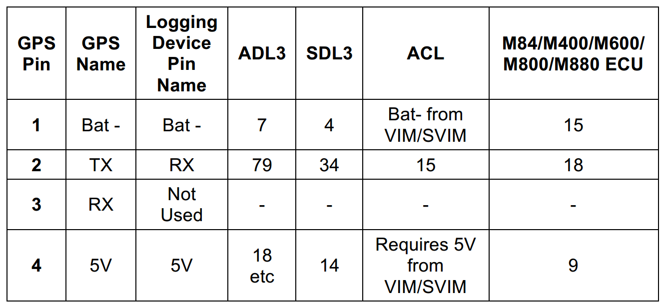
- from GPS-L5L10 Manual
- motecgpswiring.PNG (89.46 KiB) Viewed 23767 times
Re: GPS set up, M142
Posted:
Mon Mar 20, 2017 7:57 amby David Ferguson
To be clear -- connect the GPS DTM pin 2 (GPS TX) to the ECU pin A21 (ECU RS_232 RX).
Re: GPS set up, M142
Posted:
Mon Mar 20, 2017 8:53 amby Stephen Dean
As David said, you need to have Pin A-21 RS232_RX connected to pin 2 on the GPS DTM connector.
Re: GPS set up, M142
Posted:
Mon Mar 20, 2017 9:38 amby plohl
Thanks everyone, now I see I completely stuffed up.
It should be wired as followed:
DTM Pin 1 > A25 - BAT_NEG4 Battery Negative
DTM Pin 2 > A21 - RS232_RX (as this is the receive side of the ECU - it receives the transmit side from the GPS unit)
DTM Pin 3 > Nothing (as the ecu is not transmitting anything for the GPS unit for it to receive?)
DTM Pin 4 > A18 SEN_5V0_C2 Sensor 5.0V C
well... I hope that will work.
Re: GPS set up, M142
Posted:
Mon Mar 20, 2017 8:01 pmby plohl
so i swapped the wires so A21 is now connected to pin2 on the gps.... still a timeout error. Sat the car in the driveway for 10min to see if it sync up.
Will the GPS try reconnecting after the first timeout? I was expecting/hoping to see Wait for GPS fix...
Re: GPS set up, M142
Posted:
Tue Mar 21, 2017 2:40 amby David Ferguson
Have you set the GPS baud rate correctly? For the GPSL10, it's 38400 -- note that this is set under the RS232 group.
Any chance you really have a GPS L5? You might try setting the baud rate to 19200 just to check.
If you have the flashing LED on the GPS receiver, then it usually has obtained lock and has coordinates. When you are searching for GPS lock, the GPS date & time will be the first fields to populate with reasonable values. That's what I usually look for when connecting to a dash.
Re: GPS set up, M142
Posted:
Tue Mar 21, 2017 9:44 amby plohl
Thanks David.
I checked everything again this morning.
4.97V
GPS rate is 38400
Check the gps and it's serial number, PN 41304, SN 164212685 - model GPS-L10.
None of the GPS values (date, time, etc) populate.
Still getting the LED flash on the GPS.
I didn't have the CAN rate set, so changed that to 0x04. Wasn't it sure if it would make a difference, but it didn't appear too.
I have also posted the question in a tuning group on facebook. Someone there mentioned that a batch of the GPS modules didn't work with the M1's. Can anyone confirm this?
Re: GPS set up, M142
Posted:
Tue Mar 21, 2017 1:36 pmby adrian
On the bottom of the GPS it will have Locosys and then under that will be a model number. It will be either LS23036 or LS23036-G. Which one do you have?