M1 Sequential Turbos

Forum for general discussions on engine tuning, not specific to a particular motec ECU

M1 Sequential Turbos

Postby CarloL on Tue Jun 21, 2016 10:30 am

Hi

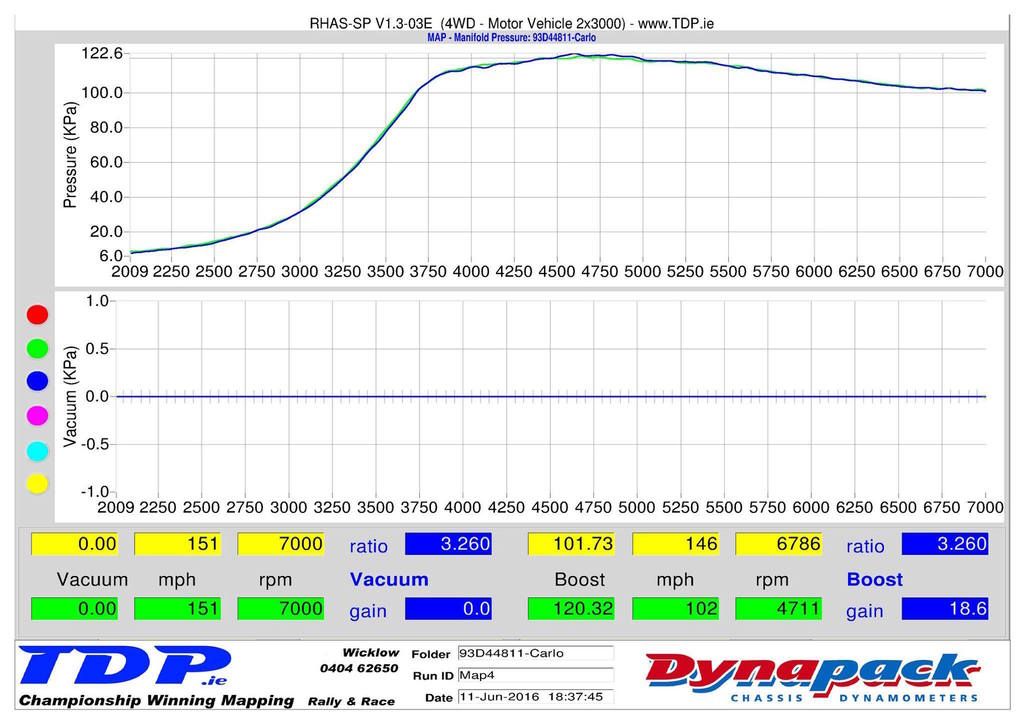
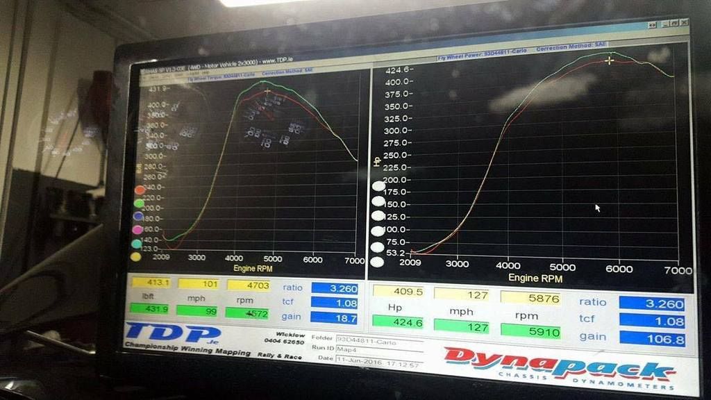
Car: Toyota Supra Twin Turbo running Sequentially, OEM Ecu the transition to the second Turbo is around 3500-3800rpm

Question:
How is the M130 setup?

My map has IACV and EGCV set to two Aux outputs , my understanding is the transition is regulated by the Manifold pressure? 350kPa , constantly turbo one is working , when Manifold Absolute pressure hits 350kPa , turbo two comes online? can you calculate this into RPM?

Maybe I am looking in the wrong area but I cannot find anything in the M1 Tune to indicate EGCV opens at a certain RPM? But was told it is around 3800 it happens , my Dyno Graph looks too linear power delivery to suggest the ECU is running the tubbies sequentially

How the OEM System works
Actuators and VSVs:

They are not pulse width modulated save for the wastegate one. So the other 3 are either open or closed. The wastegate one is PWM controlled.

There are four VSV/actuator assemblies that control the sequential turbo operation:
[*]Intake Air Control Valve (IACV)
[*]Exhaust Gas Control Valve (EGCV)
[*]Exhaust Gas Bypass Valve (EGBV)
[*]Wastegate

VSVs switch manifold pressure (boost) to and away from actuators. The actuators open/shut valve butterfly flaps.

IACV
When this switches, boost generated by #2 turbo is allowed to join the intake stream
When it isn't switched, there is a small flap in the IACV assembly that allows any boost generated by #2 turbo as it prespools to join the intake stream, preventing turbo stall.

EGCV
This allows exhaust gas to flow through #2 turbo, causing it to spin up. When it's shut, there is no gas flow through the impeller of #2 turbo and therefore it doesn't spin.

EGBV
This allows some exhaust gas to bypass the EGCV and join the output of the first turbo. It serves two purposes - one, it prespools the second turbo by allowing some exhaust gas flow through it. Two, it controls the amount of exhaust gas going through the first turbo in much the same way as a wastegate - therefore controlling the maximum boost pressure generated by #1 turbo.

Wastegate
This bypasses exhaust gas from the first turbo, lowering the overall amount of exhaust gas going through *both* turbos and controlling the maximum boost pressure generated by both turbos in parallel.

ECU Setup

Image

DYNO's

Image

Image
CarloL
 
Posts: 105
Joined: Thu Nov 05, 2015 2:00 am

Re: M1 Sequential Turbos

Postby Stephen Dean on Tue Jun 21, 2016 5:38 pm

Hi Carlo,

Looking at the data shown, why do you have the transition point so high? according to the screenshot of the MAP trace, you are 230kPa away from the point that you want the Aux Output to work at, thus it will not open the valves. What happens if you lower the transition point to a pressure closer to that that the engine is actually making?

Also,

How do you have the Duty Cycle table filled out? that is what actually controls the valve.
Stephen Dean
MoTeC Research Centre Melbourne, Australia
User avatar
Stephen Dean
Site Admin
 
Posts: 1787
Joined: Tue Dec 02, 2014 10:29 am
Location: Melbourne

Re: M1 Sequential Turbos

Postby CarloL on Wed Jun 22, 2016 1:08 am

Thanks Stephen ,

I am not too sure why the max MAP pressure is set to 350kPa, my mapper did it

MAP Trace

My understanding, 350kPa is just setting to control when the input is enabled or disabled , so if map pressure is outside 0 and 350 , it is disabled , I presume for safety? , shuts down turbo 2 but to be honest I think it is set too high , it should shut down at 1.2 bar as you stated


Duty Cycle

Have not looked at the duty table but here's my understanding, The duty cycle determines how long the solenoid bleeds the system over a period of Time , considering we are talking about valves to route the exhaust gas to turbo X , turbo one should have a high duty cycle throughout the Rev range ( or inverted polarity takes care of this) , turbo 2 should have a low duty cycle in low revs till pressure builds up , then turbo 2 VSV is opened (increase in duty cycle) , a boost target is set 1.25 , with a boost error trim tables to be used as adjustment in reaching target boost, duty cycle can be set by throttle position and rpm axis

I will post up the duty tables later

thanks
CarloL
 
Posts: 105
Joined: Thu Nov 05, 2015 2:00 am

Re: M1 Sequential Turbos

Postby CarloL on Wed Jun 22, 2016 4:11 am

Image

Image
CarloL
 
Posts: 105
Joined: Thu Nov 05, 2015 2:00 am

Re: M1 Sequential Turbos

Postby CarloL on Wed Jun 22, 2016 4:14 am

Image
CarloL
 
Posts: 105
Joined: Thu Nov 05, 2015 2:00 am

Re: M1 Sequential Turbos

Postby CarloL on Tue Jun 28, 2016 2:07 am

Can Anybody explain how the above code is work?
I do not think my line of taught is correct
thanks!
CarloL
 
Posts: 105
Joined: Thu Nov 05, 2015 2:00 am


Return to Tuning discussions

Who is online

Users browsing this forum: No registered users and 2 guests