Turbine rpm sensor logging
Hi All,
need help to setup the turbine rpm sensor in my M400.
Data from manufacturer.
----------------------------------------------------------------------------------------------------------------
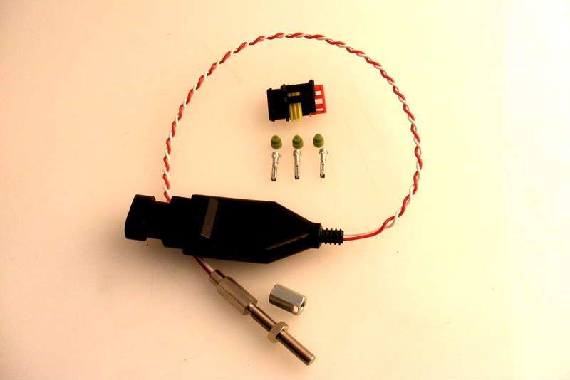
The sensor is a TS180.
Red +12V supply (min 8V max 15 volts) at approx 30mA
Black Ground (negative battery terminal)
White Data Logger / Tachometer drive (blade frequency divided by 10N where ‘N’ can be programmed between 1 and 32. Open collector output with 2K2 pullup to +12V
Use with Data Loggers
A turbine speed of 180,000 rpm with a 14 blade turbo has a blade frequency of 42,000 Hz. The module divides this by 10 and then by ‘N’ to give an output frequency that can be fed into data loggers. The software settings required in the Data Logger software for some values of ‘N’ are shown below.
TS-180 Output Frequency
(14 blades at 180,000 rpm) Data Logger Software Settings to log as Turbo RPM
‘N’ TS-180 Output Frequency Teeth Multiplier
1 4200 Hz 14 10
2 2100 Hz 7 10
14 300 Hz 1 10
N can be set to other values if needed to better match the frequency range.
----------------------------------------------------------------------------------------------------------------------
As far as I understand i have to connect white wire to a digital input, given that it's a 5V square wave.
What else to do to setup it?
Is it correct to:
Type: 2 RPM Measure
Calibration: 4200 with "N"=1 ?
Active edge: ?
Noise window: ?
Noise increment: ?
Noise limit: ?
Thanks in advance.
need help to setup the turbine rpm sensor in my M400.
Data from manufacturer.
----------------------------------------------------------------------------------------------------------------
The sensor is a TS180.
Red +12V supply (min 8V max 15 volts) at approx 30mA
Black Ground (negative battery terminal)
White Data Logger / Tachometer drive (blade frequency divided by 10N where ‘N’ can be programmed between 1 and 32. Open collector output with 2K2 pullup to +12V
Use with Data Loggers
A turbine speed of 180,000 rpm with a 14 blade turbo has a blade frequency of 42,000 Hz. The module divides this by 10 and then by ‘N’ to give an output frequency that can be fed into data loggers. The software settings required in the Data Logger software for some values of ‘N’ are shown below.
TS-180 Output Frequency
(14 blades at 180,000 rpm) Data Logger Software Settings to log as Turbo RPM
‘N’ TS-180 Output Frequency Teeth Multiplier
1 4200 Hz 14 10
2 2100 Hz 7 10
14 300 Hz 1 10
N can be set to other values if needed to better match the frequency range.
----------------------------------------------------------------------------------------------------------------------
As far as I understand i have to connect white wire to a digital input, given that it's a 5V square wave.
What else to do to setup it?
Is it correct to:
Type: 2 RPM Measure
Calibration: 4200 with "N"=1 ?
Active edge: ?
Noise window: ?
Noise increment: ?
Noise limit: ?
Thanks in advance.