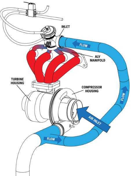
ORB map example for fresh-air antilag?

Discussion and support for MoTeC's previous generation ECUs.

ORB map example for fresh-air antilag?

Postby cotje on Wed Apr 24, 2024 8:06 am

I switched my antilag system from Throttle bypass (EGR valve) to Fresh-air (Turbosmart eALV40+Blackbox). Problem now is that I cannot get it to work as good as it did with the old system which was producing up to 0.5 bar.
Piping, connection and monitoring wise I can confirm the new eALV is activated and working as it should, so I'm now focusing on the existing values in the ORB-tables. Old values:
- Cut: 15 to 35
- Retard: -20 to -45
- Air: always 100% opened (Status Control)
- Fuel: 0 to 5

Using these with the new eALV does not result in the same amount of boost generated and I assumably should use other values. The eALV is expected to provide a lot more air in comparison to the old EGR-valve (probably 4 times more). Current values that generate some ORB effect (0.1 bar) are:
- Cut: 10 to 20
- Retard: -10 to -15
- Air: 100% opened when ORB active (for now via Aux-table)
- Fuel: 0 to 5

However, for the amount of air the eALV passes, I'm expecting a lot more boost!

Can someone share experiences or example ORB-maps for fresh-air anti-lag?
Image
cotje
 
Posts: 70
Joined: Mon Oct 07, 2013 5:50 am

Re: ORB map example for fresh-air antilag?

Postby Stephen Dean on Wed Apr 24, 2024 12:55 pm

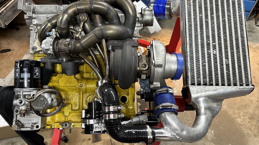
The design of that feed from the intercooler pipework into the silicon hose it not conducive to flow into the valve, if any thing, a cut like that is going to be drawing mass flow from the valve into the inlet tract.
Stephen Dean
MoTeC Research Centre Melbourne, Australia
User avatar
Stephen Dean
Site Admin
 
Posts: 1614
Joined: Tue Dec 02, 2014 10:29 am
Location: Melbourne

Re: ORB map example for fresh-air antilag?

Postby cotje on Wed Apr 24, 2024 5:14 pm

Stephen Dean wrote:The design of that feed from the intercooler pipework into the silicon hose it not conducive to flow into the valve, if any thing, a cut like that is going to be drawing mass flow from the valve into the inlet tract.


Thanks Stephen! I think I understand what you say. This was the shortest way to connect the ic-piping to the eALV with the assumption the air-pressure has no way to go other than to this valve (throttle is closed). We took the below example where the piping is at 90deg.

From what I understand from https://www.hpacademy.com/blog/aggressive-anti-lag-theory-fresh-air-als-mountune-tech-nugget/, it's not so much about cut/retard anymore (to suppress the engine pushing), but more about adding enough fuel. Did not test it as of yet though.

Image
cotje
 
Posts: 70
Joined: Mon Oct 07, 2013 5:50 am

Re: ORB map example for fresh-air antilag?

Postby Stephen Dean on Wed Apr 24, 2024 5:44 pm

If there is enough pressure on the cold side to over power the pressure in the hot side, then you should get flow through the ALV, but if the cold side pressure is lower than the hot side, you will have exhaust gases flowing into the cold side of the system. Or does the ALV have one way poppet valves to prevent this back flow from occurring?
Stephen Dean
MoTeC Research Centre Melbourne, Australia
User avatar
Stephen Dean
Site Admin
 
Posts: 1614
Joined: Tue Dec 02, 2014 10:29 am
Location: Melbourne

Re: ORB map example for fresh-air antilag?

Postby cotje on Wed Apr 24, 2024 6:03 pm

Good question! Not sure what pressures to expect on the hot side. On the cold side I'm running between 1.2 and 2.0 bar. Once the throttle closes ORB activates and the eALV (just a electronic DWB actuated waste-gate valve), that cold side pressure should easily (in my mind ;) ) flow into the hot side. I was expecting to miss the correct cut/retard/fuel values to really ignite the mixture. This reasoning is supported by the fact we do not see EGT rising very much. The old system easily went up to 1000deg.
cotje
 
Posts: 70
Joined: Mon Oct 07, 2013 5:50 am


Return to M400, M600, M800 and M880 ECUs

Who is online

Users browsing this forum: No registered users and 10 guests