Stupid Motec tricks- making a timer loop.
Why? Because I needed to run an unattended oil/engine preheater. Timer 1 ran the heating element via another aux table to DC% the heater vs temp, Timer 2 circulated the oil via an electric pump. Might have other uses. Just demonstrates the flexibility of an ECU that allows you to put nearly anything as a table axis.
What is needed- One switched input, one output, and both timers.
Since the timers increment to max value and stay there until their status has been reset, a timer can't run continuously, so we use the second timer to reset the first. Now both timers will increment to max alternately in a continuous loop, and output tables can be assigned to both or either timer.
An available dig 1-4 or switch 1-6.
This switched input triggers the timer state, see timer setup parameter "Timer X Selection" and set to this channel.
Timer 1 needs to be opposite polarity of Timer 2 in timer setup parameter "Timer X Logic Polarity". As the aux table in the output switches from on to off the timers increment alternately. NOTE: You can have the Timer 1 reset nearly instantly by having very small Timer 2 increments in the table, .00, .01, and a Timer 2 Max of .02
An output, aux/ign/inj doesn't matter.
Wire this output into the switched input selected above. Set up an aux table with Timer 1 and Timer 2 as axes, set up a table that looks something like this-
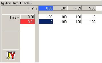
Timer 1 starts and increments to 4.995 seconds and output turns off, this changes the state of the dig/switch input status flag, timer 2 starts and increments to .005 seconds and stops, output changes switch state back in a continuous loop, as long as ECU is in an on state. Set your timer axis values and timer max values to whatever length is needed, up to 327.67 seconds.