My Honda Insight uses a 12 tooth trigger on the crank (no gaps or additional teeth).
The cam uses two teeth, arranged as if there were three teeth at 120 degree intervals but with one missing. Two separate cam sensors are used - TDC #1 and TDC #2.
How do I use this system on the MoTeC M400?
The Honda S2000 uses a similar approach, but with three teeth on the cam not the Insight's two teeth. (The Hundred series ECUs have a specific mode for the S2000.)
Note that in the Insight the two teeth are cast into the cam, so removing one tooth would be a reasonably major exercise.
Thanks for any help anyone can offer.
Honda crank and cam signals
10 posts
• Page 1 of 1
Honda crank and cam signals
![]() by JulianEdgar on Sat Jul 12, 2014 9:31 am
by JulianEdgar on Sat Jul 12, 2014 9:31 am
- JulianEdgar
- Posts: 57
- Joined: Sat Aug 17, 2013 6:38 pm
Re: Honda crank and cam signals
![]() by J&R on Sat Jul 12, 2014 6:56 pm
by J&R on Sat Jul 12, 2014 6:56 pm
Choose the Honda s2000 Ref/sync mode
its Number 64 in the ref sync menu that is in the help file of ECU manager OEM Modes Use F1
its Number 64 in the ref sync menu that is in the help file of ECU manager OEM Modes Use F1
- J&R
- Posts: 20
- Joined: Sun Jul 20, 2008 8:48 pm
Re: Honda crank and cam signals
![]() by AdamW on Sun Jul 13, 2014 9:57 am
by AdamW on Sun Jul 13, 2014 9:57 am
J&R: S2000 wont work, they have a 4-1 sync, this engine has a 3-1.
Julian: A 3-1 sync is fairly unique, I dont think there are any existing modes that will work with this. If you dont want to remove a tooth off the cam then there are really only two other quick options;
1. Grind one tooth off crank wheel, run it in batch fire mode and dont use sync at all.
2. Add a new sync tooth/sensor somewhere that is easier to access - say a lug on the cam sprocket or something.
Motorsport Electronics Ltd.
- AdamW
- Pro User
- Posts: 265
- Joined: Wed Nov 16, 2011 10:08 am
Re: Honda crank and cam signals
![]() by JulianEdgar on Mon Jul 14, 2014 9:16 am
by JulianEdgar on Mon Jul 14, 2014 9:16 am
I have had a thought.
The two cam sensors are spaced at the same angle as the two teeth. That is, only once per cam rotation do both sensors develop an output simultaneously. (At other times only one sensor or the other is developing an output.)
They are inductive sensors.
If I parallel the two sensors, wouldn't then a stronger output be developed only once per cam rotation?
That is, once per cam rotation, a single wave of greater amplitude would be developed.
And couldn't I then use the synch mag levels to filter out the lower amplitude waves, allowing the ECU to see only the single larger wave per cam rotation?
Scope display of both cam sensors:
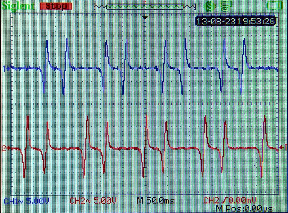
Thoughts?
The two cam sensors are spaced at the same angle as the two teeth. That is, only once per cam rotation do both sensors develop an output simultaneously. (At other times only one sensor or the other is developing an output.)
They are inductive sensors.
If I parallel the two sensors, wouldn't then a stronger output be developed only once per cam rotation?
That is, once per cam rotation, a single wave of greater amplitude would be developed.
And couldn't I then use the synch mag levels to filter out the lower amplitude waves, allowing the ECU to see only the single larger wave per cam rotation?
Scope display of both cam sensors:
Thoughts?
- JulianEdgar
- Posts: 57
- Joined: Sat Aug 17, 2013 6:38 pm
Re: Honda crank and cam signals
![]() by AdamW on Mon Jul 14, 2014 12:56 pm
by AdamW on Mon Jul 14, 2014 12:56 pm
I like that you are thinking outside the square…
While your theory that the paralleled VR sensors would give you one ‘big’ pulse per cycle seems plausible, I think however the large variation in amplitude Vs RPM will be what is difficult to work with.
If I’m reading your scope trace correctly, it looks like at idle speeds you have about 15V peak to peak. If you parallel the sensors this voltage will roughly double. The Motec allows you to set a sensor level (arming voltage) of up to about 9.5Vmax, then you also have the ‘trigger voltage’ setting that you could possibly use to leverage a little more offset so I would say you may actually be able to get this to work at low RPM. The problem will come however at higher RPM when you will have more like 50V p to p so that will present a bit more of a challenge. There is possibly some external conditioning circuit options that could be built but I personally would be looking for a more robust solution.
Motorsport Electronics Ltd.
- AdamW
- Pro User
- Posts: 265
- Joined: Wed Nov 16, 2011 10:08 am
Re: Honda crank and cam signals
![]() by JulianEdgar on Mon Jul 14, 2014 2:04 pm
by JulianEdgar on Mon Jul 14, 2014 2:04 pm
Use a voltage divider on input? That way, the relationship between min and max levels with variation in rpm could be same as with one sensor.
I am trying to set it up now - but one of the cam sensor signals isn't getting to ECU. Checking continuity of wiring.
I am trying to set it up now - but one of the cam sensor signals isn't getting to ECU. Checking continuity of wiring.
- JulianEdgar
- Posts: 57
- Joined: Sat Aug 17, 2013 6:38 pm
Re: Honda crank and cam signals
![]() by JulianEdgar on Tue Jul 15, 2014 6:49 am
by JulianEdgar on Tue Jul 15, 2014 6:49 am
Wasn't happy with setting levels to trigger only when the 'big pulse' came around - AdamW, you were right. 
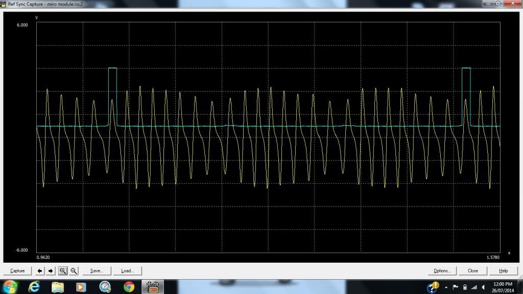
I now have eLabtronics building an interface that triggers an output only when both cam sensors are developing an output (ie once per camshaft rotation).
I now have eLabtronics building an interface that triggers an output only when both cam sensors are developing an output (ie once per camshaft rotation).
- JulianEdgar
- Posts: 57
- Joined: Sat Aug 17, 2013 6:38 pm
Re: Honda crank and cam signals
![]() by JulianEdgar on Tue Aug 05, 2014 9:09 am
by JulianEdgar on Tue Aug 05, 2014 9:09 am
http://www.elabtronics.com/ interface module works perfectly. Takes inputs from two cam sensors sensing two teeth per rev and outputs fast response square wave, once per cam rotation. (click on image to get full screen grab.)

- JulianEdgar
- Posts: 57
- Joined: Sat Aug 17, 2013 6:38 pm
Re: Honda crank and cam signals
![]() by AdamW on Wed Aug 06, 2014 11:12 am
by AdamW on Wed Aug 06, 2014 11:12 am
Looks good!
As long as that sync doesn't shift too much with RPM you should be good.
May I ask what you are getting up to with a Honda insight? - You don't see too many hybrids with a Motec...
As long as that sync doesn't shift too much with RPM you should be good.
May I ask what you are getting up to with a Honda insight? - You don't see too many hybrids with a Motec...
Motorsport Electronics Ltd.
- AdamW
- Pro User
- Posts: 265
- Joined: Wed Nov 16, 2011 10:08 am
Re: Honda crank and cam signals
![]() by JulianEdgar on Wed Aug 06, 2014 12:58 pm
by JulianEdgar on Wed Aug 06, 2014 12:58 pm
Triggering off rising edge of sync pulse is working well - sweet to 6000 rpm which is what I want.
I am modifying a 2001 Honda Insight to try achieve a really outstanding performance/ economy compromise.
First step: M400 engine management, CDL3 dash, turbo, water/air intercooling, 12 hole injectors, Bosch MEC-723 coils, variable flow exhaust. Run as non-hybrid.
Second step: new HV li-ion battery pack, new electric motor controller
Car has drag coefficient of 0.25, small frontal area and aluminium body weighs 850kg. Final aim is for open road fuel economy in Twos (litres/100km) and 0-100 km/h in Sixes.
- JulianEdgar
- Posts: 57
- Joined: Sat Aug 17, 2013 6:38 pm
10 posts
• Page 1 of 1
Return to M400, M600, M800 and M880 ECUs
Who is online
Users browsing this forum: No registered users and 17 guests