Hi All,
need help to setup the turbine rpm sensor in my M400.
Data from manufacturer.
----------------------------------------------------------------------------------------------------------------
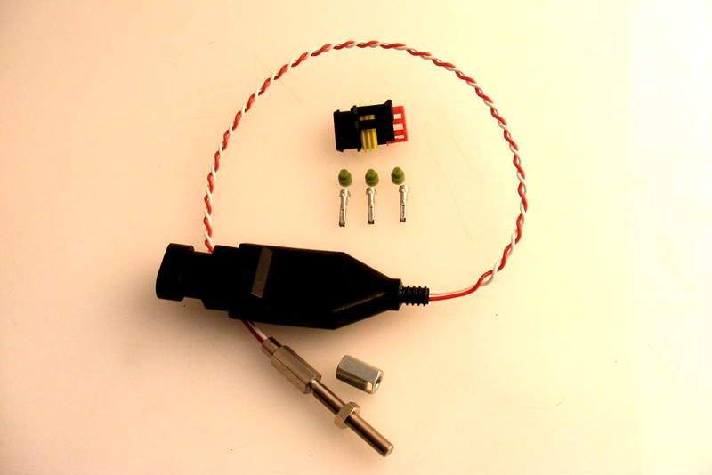
The sensor is a TS180.
Red +12V supply (min 8V max 15 volts) at approx 30mA
Black Ground (negative battery terminal)
White Data Logger / Tachometer drive (blade frequency divided by 10N where ‘N’ can be programmed between 1 and 32. Open collector output with 2K2 pullup to +12V
Use with Data Loggers
A turbine speed of 180,000 rpm with a 14 blade turbo has a blade frequency of 42,000 Hz. The module divides this by 10 and then by ‘N’ to give an output frequency that can be fed into data loggers. The software settings required in the Data Logger software for some values of ‘N’ are shown below.
TS-180 Output Frequency
(14 blades at 180,000 rpm) Data Logger Software Settings to log as Turbo RPM
‘N’ TS-180 Output Frequency Teeth Multiplier
1 4200 Hz 14 10
2 2100 Hz 7 10
14 300 Hz 1 10
N can be set to other values if needed to better match the frequency range.
----------------------------------------------------------------------------------------------------------------------
As far as I understand i have to connect white wire to a digital input, given that it's a 5V square wave.
What else to do to setup it?
Is it correct to:
Type: 2 RPM Measure
Calibration: 4200 with "N"=1 ?
Active edge: ?
Noise window: ?
Noise increment: ?
Noise limit: ?
Thanks in advance.
Turbine rpm sensor logging
6 posts
• Page 1 of 1
Turbine rpm sensor logging
![]() by Wolf_Tm250 on Wed Feb 10, 2010 3:02 am
by Wolf_Tm250 on Wed Feb 10, 2010 3:02 am
Wolf_Tm
Toyota Celica GT-four ST205 - full TTE/WRC hardware
Parma - Italy
http://www.youtube.com/user/WolfTm250
Toyota Celica GT-four ST205 - full TTE/WRC hardware
Parma - Italy
http://www.youtube.com/user/WolfTm250
- Wolf_Tm250
- Posts: 127
- Joined: Fri Jul 11, 2008 1:40 am
- Location: Parma - Italy
Re: Turbine rpm sensor logging
![]() by Scott@FP on Fri Feb 12, 2010 7:12 am
by Scott@FP on Fri Feb 12, 2010 7:12 am
The ones we use its real simple, just a couple of absolutes- can't go over 6KHz at the ECU digital input. Can't display RPM's above 20,000. Can't have a speed/RPM cal value above 19999, and cal value must be a whole number from 1-19999.
Workaround is to configure your speed input to display in RPM x 1000 (or RPM x 100).
For instance in your dig input function setup, use RPM, and for a sensor that has an internal div/8 function and a display RPM in whole thousands the cal would be;
(sensed blade count/divider circuit output factor)*1000
14 blades/8 = 1.75*1000=1750
enter '1750' in digital input function/calibration field.
12 blades/10 = 1.2*1000 = 1200
etc.
The units we use output one 100uS 5v pulse per 8 blades, are 6mm x .50 threads and 40mm length.
(edit to correct thread pitch)
I've never had to use any of the noise parameters, the ONLY problems we've ever seen is from sensor to blade gap being too CLOSE, it then sometimes picks up stray 'doubles'.
Last edited by Scott@FP on Fri Feb 19, 2010 11:41 am, edited 1 time in total.
- Scott@FP
- Posts: 421
- Joined: Thu Jul 10, 2008 7:57 pm
Re: Turbine rpm sensor logging
![]() by stevieturbo on Mon Feb 15, 2010 9:32 pm
by stevieturbo on Mon Feb 15, 2010 9:32 pm
Just spied this
http://www.oxfordrfsensors.com/products.html
How much was the sensor Wolf ? Does it need any form of external controller ? Or just a power supply ?
http://www.oxfordrfsensors.com/products.html
How much was the sensor Wolf ? Does it need any form of external controller ? Or just a power supply ?
- stevieturbo
- Posts: 503
- Joined: Fri Jul 11, 2008 3:32 am
Re: Turbine rpm sensor logging
![]() by Wolf_Tm250 on Tue Feb 16, 2010 1:00 am
by Wolf_Tm250 on Tue Feb 16, 2010 1:00 am
stevieturbo wrote:Just spied this
http://www.oxfordrfsensors.com/products.html
How much was the sensor Wolf ? Does it need any form of external controller ? Or just a power supply ?
Yes, it's what I have...
I don't remember... 250£ plus shipping?
It has an external controller...
Wolf_Tm
Toyota Celica GT-four ST205 - full TTE/WRC hardware
Parma - Italy
http://www.youtube.com/user/WolfTm250
Toyota Celica GT-four ST205 - full TTE/WRC hardware
Parma - Italy
http://www.youtube.com/user/WolfTm250
- Wolf_Tm250
- Posts: 127
- Joined: Fri Jul 11, 2008 1:40 am
- Location: Parma - Italy
Re: Turbine rpm sensor logging
![]() by Scott@FP on Wed Feb 17, 2010 8:29 am
by Scott@FP on Wed Feb 17, 2010 8:29 am
The sensor we're using costs $225.00 USD in kit form, 3 wires +5v, 0v and signal, uses a standard AMP SSC connector. Electronics are contained in the molded connector.
- Scott@FP
- Posts: 421
- Joined: Thu Jul 10, 2008 7:57 pm
Re: Turbine rpm sensor logging
![]() by Wolf_Tm250 on Wed Feb 17, 2010 5:24 pm
by Wolf_Tm250 on Wed Feb 17, 2010 5:24 pm
Scott@FP wrote:The ones we use its real simple, just a couple of absolutes- can't go over 6KHz at the ECU digital input. Can't display RPM's above 20,000. Can't have a speed/RPM cal value above 19999, and cal value must be a whole number from 1-19999.
Workaround is to configure your speed input to display in RPM x 1000 (or RPM x 100).
For instance in your dig input function setup, use RPM, and for a sensor that has an internal div/8 function and a display RPM in whole thousands the cal would be;
(sensed blade count/divider circuit output factor)*1000
14 blades/8 = 1.75*1000=1750
enter '1750' in digital input function/calibration field.
12 blades/10 = 1.2*1000 = 1200
etc.
The units we use output one 100uS 5v pulse per 8 blades, are 6mm x 1.00 threads and 40mm length.
I've never had to use any of the noise parameters, the ONLY problems we've ever seen is from sensor to blade gap being too CLOSE, it then sometimes picks up stray 'doubles'.
Perfect, thanks!
Wolf_Tm
Toyota Celica GT-four ST205 - full TTE/WRC hardware
Parma - Italy
http://www.youtube.com/user/WolfTm250
Toyota Celica GT-four ST205 - full TTE/WRC hardware
Parma - Italy
http://www.youtube.com/user/WolfTm250
- Wolf_Tm250
- Posts: 127
- Joined: Fri Jul 11, 2008 1:40 am
- Location: Parma - Italy
6 posts
• Page 1 of 1
Return to M400, M600, M800 and M880 ECUs
Who is online
Users browsing this forum: No registered users and 30 guests